Lead-in Part
A piping and instrumentation diagram (P&ID) helps understand different components of any process industry. With the help of P&IDs, project engineers easily understand the piping instruments while grasping the knowledge of how different processes are interconnected within a particular project. One understands the process and flow by learning in depth about P&ID symbols, like the control system, pressure rating, piping details, and other important information that influence the control of the entire system. As per universal guidelines, a process flow industry requires access to all the P&IDs when they start building the control system.
Apart from identifying the process of a system, piping and instrumentation diagrams help the maintenance team to make certain modifications. Since everything related to the piping is laid out on a map, it substantially reduces the time and complexities a system engineer might face while performing any maintenance.
It should be noted here that creating a piping and instrumentation diagram is very complicated, and if you do not use a professional tool like EdrawMax, chances are that you might end up using incorrect P&ID symbols. Whenever you plan to create a piping and instrumentation diagram, always remember to consider such powerful tools. Before we go and help you create a P&ID, let us guide you on how to read a piping and instrumentation diagram easily.
How to Read P&IDs
If someone is starting with a piping and instrumentation diagram, they might feel that reading a P&ID becomes a little complicated if not started in the right order. Since P&ID helps understand a system’s overall process, students or maintenance engineers must know every process and component that influences the system.
When dealing with piping and instrumentation diagrams, a process engineer must follow the universal guidelines to avoid unnecessary mistakes. For example:
- In P&ID, the first letter depicts the parameter that is being controlled in the system or something that process engineers are currently accessing. We use the predefined codes to identify certain parameters, like Analysis is defined as A, Flow is defined as F, and Temperature is mapped as T.
- In P&IDs, the second letter helps understand the type of control devices used in the system. Valve, Transmitter, and Controller are the most common control devices.
- When we have to illustrate a number, we always depict them using the logical numerator.
- Most process engineers suggest that in P&ID, we also should consider adding the tag numbers. In P&IDs, we use alphabets and numbers to denote the tag numbers.
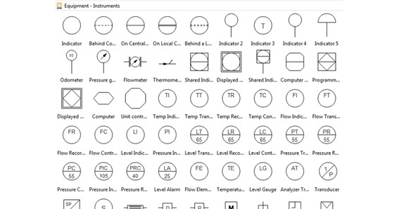
Apart from understanding the elements and letters defined by ISA standards, it is always considered a good habit to master the important abbreviations used when drawing P&IDs. Some of the most commonly used P&ID abbreviations are:
- FC: Flow Controller
- LC: Level Controller
- LG: Level Gauge
- LA: Level Alarm
- FT: Flow Transmitter
- LAL: Level Alarm Low
- PIC: Pressure Indicator & Controller
- TIC: Temperature Indicator & Controller
- PSV: Pressure Safety Valve
- TW: Thermowell
- RV: Relief Valve
- USD: Unit Shutdown
How to Draw a Piping and Instrumentation Diagram Effortlessly?
Drawing a piping and instrumentation diagram using software becomes very easy. If one tends to draw P&ID using traditional methods, chances are that their design would lack technicalities and might suffer in the long term. Keeping that in mind, it is recommended to use a P&ID tool like EdrawMax to create your piping and instrumentation diagrams. Check out the following steps to draw P&ID quickly:
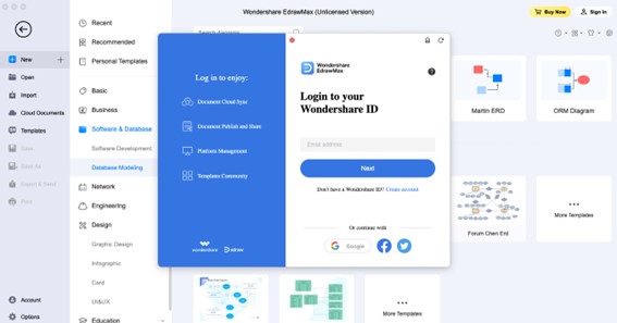
- Download EdrawMax: Head to EdrawMax’s official website and download this all-in-one diagramming tool. Once downloaded to your system, you can register using different sign-up methods. This way, you can easily save your file to a personal cloud for future usage.
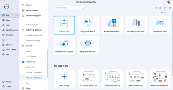
On this diagramming tool’s homepage, you will see 280+ different diagram categories. Head to the ‘Engineering’ diagram type and click on ‘Industrial Engineering,’ followed by selecting ‘Process P&ID.’ This way, you can easily access the system-generated P&Id symbols or templates.
- Template Access: Head to the ‘Templates’ section on the homepage and search for ‘P&ID’ in the template community section. You will find over 1500+ user-generated templates in this template community that you can instantly use.
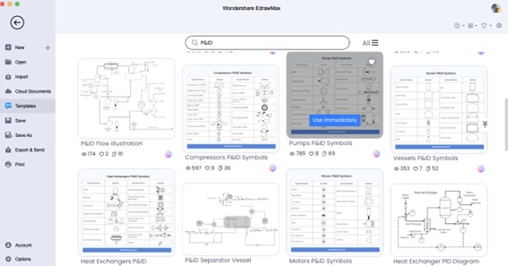
Some of the most used P&ID templates are P&ID flow illustration, Motors P&ID symbols, and more. Check these templates and click on ‘Use Immediately’ if you plan to access the content of these user-generated templates.
- Build from Scratch: If you are an experienced process engineer and know your way around P&ID symbols, you can head to ‘Process P&ID’ and click on ‘+’ to start creating the piping and instrumentation diagram from scratch. Start placing the right components in the right places. Start by defining the scope of work, learning about the flow’s inputs and outputs, listing the equipment, defining the relationship between different P&ID components, and adding further details.
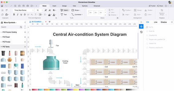
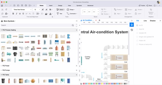
- Add Details or Customize: EdrawMax has 26,000+ vector-enabled symbols that help create technically correct diagrams. Access these templates to add details to your P&ID. With the built-in customization options, you can modify each component’s color, change the text size and font, import your media files, replace the shapes, and more. This way, your P&ID would be highly unique and technically correct.
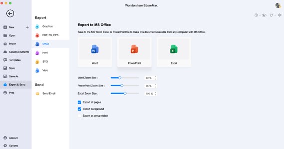
- Export & Share: After you are satisfied with your P&ID, you can export the diagram into multiple formats, like JPEG, PNG, PDF, HTML, SVG, and more. EdrawMax also lets you export the P&ID into Microsoft format for better collaboration. With the built-in sharing options, you can even share your piping and instrumentation diagram on Facebook, Twitter, Pinterest, and Line.
Final Thoughts
Creating piping and instrumentation diagrams can be tricky and require patients as well as knowledge of all the important P&ID components. If you are using traditional methods to draw P&ID, you might hamper the quality of your diagrams. That is why a tool like EdrawMax is highly recommended. This free P&ID software comes with free templates, symbols, online resources, personal cloud storage, remote collaboration, Visio’s import and export option, and more. If you want to learn how to read P&ID symbols and how to draw P&ID effortlessly easily, check out EdrawMax and start accessing the free template and symbol library.